Description
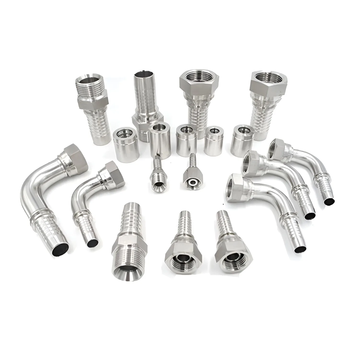
These are the fittings that are crimped onto hydraulic hose to make an assembly: a shank that enters the hose bore, a ferrule that is swaged down over the cover, and a connection end - swivel nut or male stud - in the thread form the port requires. One-piece and two-piece patterns, straight and elbowed, are all in the range.
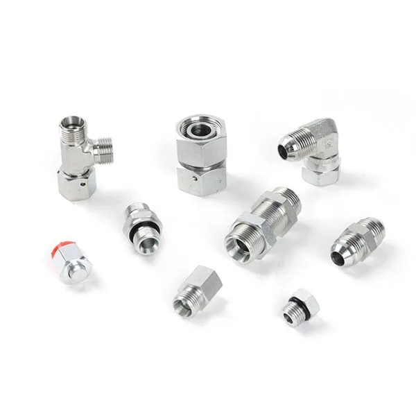
The governing standards are the ISO 12151 series, Connections for hydraulic fluid power and general use - Hose fittings. Part 1 covers O-ring face seal (ORFS) ends to ISO 8434-3, Part 2 the 24 degree cone ends with O-rings to ISO 8434-1, Part 3 the SAE 4-bolt flange ends to ISO 6162, Part 4 the ISO 6149 metric stud ends, Part 5 the 37 degree flared (JIC) ends to ISO 8434-2 and Part 6 the 60 degree cone (BSP) ends to ISO 8434-6. Between them they cover hose bores from 5 mm to 51 mm depending on the end form.
The rule that matters on site is in ISO 12151-2 clause 4.2: the working pressure of the assembly is the lower of the pressure given for the size in the connector standard and the pressure given in the hose specification. A fitting never raises the rating of a hose. ISO 12151-2 also requires the finished assembly to meet the performance requirements of the hose specification, so hose, fitting and ferrule have to be used together as the fitting maker qualifies them, at the crimp diameter that maker specifies.
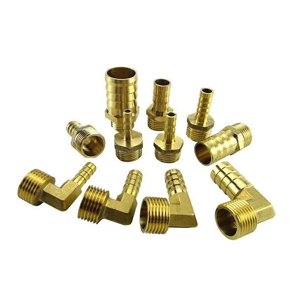
State at order: hose type and bore, end form and size, whether swivel or fixed, straight or elbow, and the fitting material. ISO 12151-2 specifies carbon steel; where stainless steel or copper alloy bodies are used, ISO 8434-1 requires the pressure and temperature rating to be defined by the manufacturer instead.