WIKA PGT43.100 / PGT43.160 intelliGAUGE® – Diaphragm Pressure Gauge with Output Signal (4–20 mA / 0–10 V)

WIKA

WIKA PGT43.100 / PGT43.160 intelliGAUGE Diaphragm Gauge

Model PGT43.100 / PGT43.160

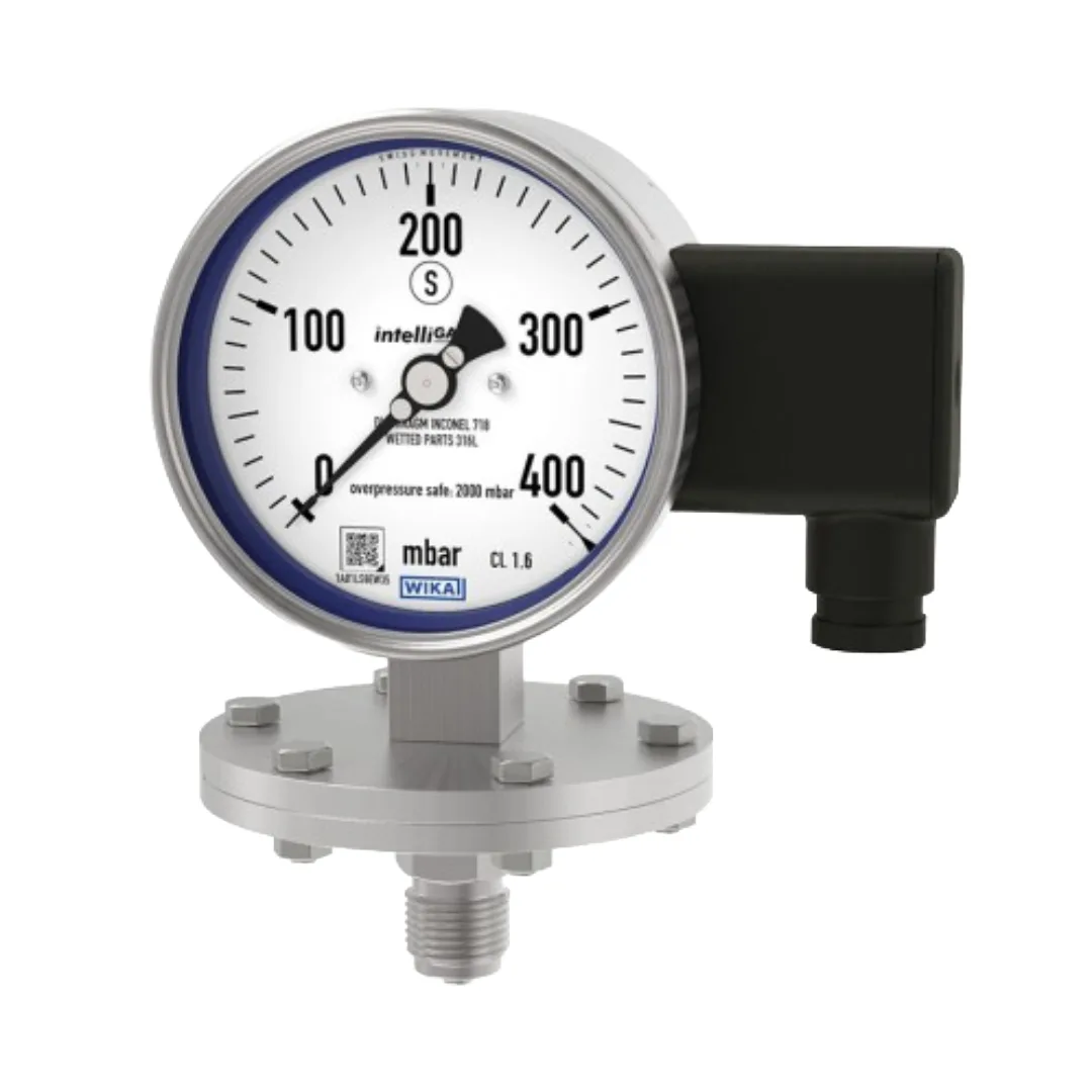
Diaphragm pressure gauge with electrical output signal for low process pressures from 0-16 mbar, with up to 10-fold overload safety and an S3 Solidfront safety case. Nominal sizes 100 and 160 mm.

Prices on request. Contact us for availability and quotations.

Documents

Need a certificate we have not listed? Ask us and we will send it.

Description

The WIKA PGT43 intelliGAUGE is the diaphragm-element member of WIKA's mechatronic gauge family. Where the PGT23 uses a Bourdon tube, the PGT43 uses a diaphragm element between measuring flanges, which is what allows it to read very low pressures - from 0 ... 16 mbar - and to survive substantial overload.

The diaphragm drives the pointer mechanically, and an electronic angle encoder proven in safety-critical automotive applications reads the pointer shaft position without contact to generate the output signal. Local indication therefore remains available whether or not the electronics are powered.

Scale ranges are 0 ... 16 mbar to 0 ... 250 mbar with the 160 mm flange, and 0 ... 400 mbar to 0 ... 30 bar with the 100 mm flange, in accuracy class 1.6 (class 1.0 on application test). Overload safety is 5 times full scale as standard, optionally up to 10 times, in both cases limited to 40 bar; vacuum safety to -1 bar is an option. The diaphragm element is stainless steel 316L up to 0.25 bar and NiCr alloy (Inconel) above it, and the process connection with lower measuring flange is stainless steel 316L.

The case is a safety version S3 per EN 837 with a solid baffle wall and blow-out back, unfilled as standard. Output variants match the PGT23: 4 ... 20 mA 2-wire per NAMUR NE 43, 4 ... 20 mA for hazardous areas, 0 ... 20 mA 3-wire and 0 ... 10 V 3-wire. Ingress protection is IP54, or IP65 with silicone oil M50 case filling. Connections are G 1/2 B, 1/2 NPT, M20 x 1.5, or open flanges DN 25 and DN 50 PN 40 to EN 1092-1 and 1" and 2" class 150 RF to ASME B16.5.
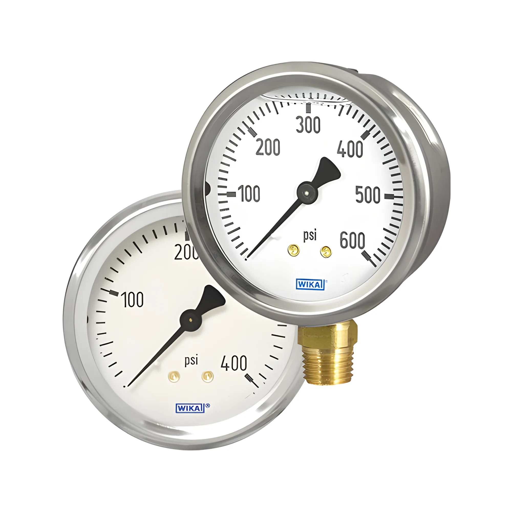
Specifications

Nominal Size 100 mm and 160 mm
Scale Range 0 ... 16 mbar to 0 ... 250 mbar (flange Ø 160 mm); 0 ... 400 mbar to 0 ... 30 bar (flange Ø 100 mm); other units and vacuum or combined ranges available
Accuracy Class 1.6; option 1.0 (application test required)
Output Signal Variant 1: 4 ... 20 mA, 2-wire, passive, per NAMUR NE 43. Variant 2: 4 ... 20 mA, 2-wire, for hazardous areas. Variant 3: 0 ... 20 mA, 3-wire. Variant 4: 0 ... 10 V, 3-wire. Signal error <= 1 % of span; linearity <= 1 % (terminal method); refresh rate 600 ms
Power Supply DC 12 V < UB <= 30 V (variants 1 and 3); DC 14 V < UB <= 30 V (variant 2); DC 15 V < UB <= 30 V (variant 4). Max. load RA <= (UB - 12 V)/0.02 A, max. 600 ohm
Overload Safety 5 x full scale value, max. 40 bar; option up to 10 x full scale value, max. 40 bar; option vacuum safety to -1 bar
Wetted Materials Diaphragm element stainless steel 316L up to 0.25 bar, NiCr alloy (Inconel) above 0.25 bar; process connection with lower measuring flange stainless steel 316L; pressure chamber sealing FPM/FKM or PTFE
Process Connection G 1/2 B, 1/2 NPT, M20 x 1.5; open connecting flange DN 25 or DN 50 PN 40 per EN 1092-1 form B; open connecting flange 1" or 2" class 150 RF per ASME B16.5; other flanges DN 15 to DN 80
Case Safety version S3 per EN 837, with solid baffle wall (Solidfront) and blow-out back; unfilled, option silicone oil M50 case filling
Permissible Temperature Medium +100 °C maximum, option +200 °C maximum; ambient -20 ... +60 °C
Ingress Protection IP54 per IEC/EN 60529; option IP65 (with silicone oil M50 case filling)